|
COMMAND EQUIPMENT
The "Command" equipment Unit 2, used in B-24D Airplane consists of the following units:
| Unit 2-1 |
One BC-458-A Transmitter, Page 112 |
| -//- 2-2 |
One BC-459-A Transmitter, Page 112
One FT-226-A Rack for 458 and 9-A Transmitters
One FT-227-A Mounting for FT-226-A Racks |
| -//- 2-3 |
One BC-453-A Receiver, Page 112 |
| -//- 2-4 |
One BC-454-A Receiver, Page 112 |
| -//- 2-5 |
One BC-455-A Receiver, Page 112
One FT-220-A Rack for BC-453-4 and 5-A Receivers
One FT-221-A Mounting for FT-22O-A Rack |
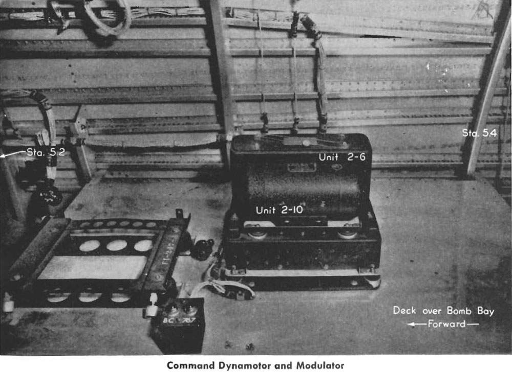
| -//- 2-6 |
One BC-456-A Modulator Unit, Page 110
One FT-225-A Mounting for Modulator Unit |
| -//- 2-7 |
One BC-442-A Antenna Switching Relay, Page 112
One FT-229-A Mounting for Relay |
| -//- 2-8 |
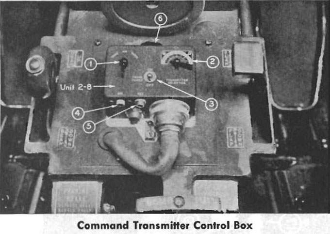
One BC-451-A Transmitter Control Box, Page 103, Page 111
One FT-228-A Mounting for Control Box
|
| -//- 2-9 |
One BC-450-A Receiver Control Unit, Page 107 |
| -//- 2-10 |
One DM-33-A Dynamotor, Page 110 |
| -//- 2-11 |
Q6202-16 Terminal Strip |
| -//- 2-12 |
DM-32-A Receiver Dynamotors |
Necessary cordages and flexible control shafts for proper inter-connection and operation of the equipment.
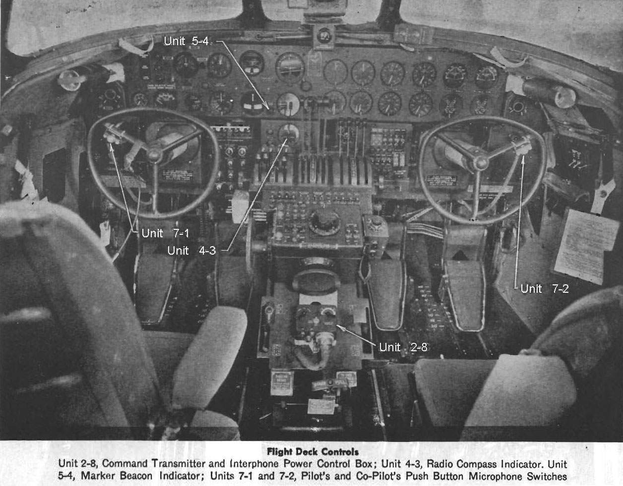
Since both mechanical and electrical control of the Command equipment is normally delegated to the Pilot and Co-Pilot, the receiver control unit, BC-450-A (Unit 2-9) is mounted on the top of the cockpit between the Pilot, and Co-Pilot; and the transmitter control unit, BC-451-A (Unit 2-8) is mounted on the pedestal.
The command set is a short range communication system used primarily for ship to ship communication. The BC-458-A transmitter has a frequency range of 5300 to 7000 KC, while the BC-459-A has a frequency range of 7000 to 9100 KC. The three receivers, namely BC-453-A, BC-454-A, and BC-455-A cover frequency ranges of 190 to 550, 3000 to 6000, and 6000 to 9100 KC respectively. No spare coils are needed for cither transmitters or receivers.
The BC-453-A, BC-454-A, and 5-A receivers Units 2-3, 2-4, 2-5, and the BC-458-A and BC-459-A transmitters Units 2-1, 2-2 (Page 112) are mounted above the wing center section just aft of the life raft area. The BC-456-A modulator unit (Unit 2-6) and the DM 33-A Dynamotor (Unit 2-10) are mounted aft of the compass receiver on the rack for the RADAR equipment (See photo below).
A terminal strip, Unit 2-11, connects the transmitter remote control unit with the modulator unit, transmitter side tone, receiver output and interphone system. It is located in the compartment above the wing center section, outboard of the Compass Receiver unit and contains terminals only.

The receiver control box (Page 107) Unit 2-9 is divided into three identical control sections, except for dial calibrations, each connected to its own receiver. Thus, command receivers can be used individually or in any combination desired by the operator. A switch (13) is located in the upper right corner of each control section and has '"CW," "MCW," and "OFF" positions. Two phone jacks marked "A-Tel," and "B-Tel" (17) are located on the aft side of the receiver control box through which receiver output and command transmitter side tone may be heard. These jacks are not normally used since the Command set is connected to the interphone system, and transmission or reception may be accomplished from any interphone station throughout the airplane as long as the Command equipment is turned "ON." Output to these jacks is controlled by the switch (12) in the upper left comer of each control marked "A"—"B." For interphone station operation turn all three switches to position "A." On the face of the BC-451-A transmitter control Unit 2-8 Page 103, Page 111, which is mounted on the pedestal, are three switches. The center switch (3) is marked "Trans. Power," "ON," "OFF."
The switch (1) on the left has three positions marked "Tone-CW-Voice." On "Tone" a keyed signal modulated at approximately 1000 cycles per second can be transmitted. "CW" is for keyed transmission of an unmodulated signal. The third position is for voice transmission. Two positions on the right hand selector switch (2) connect to the two command transmitters. The other two positions are not used.
On both "CW" and "Tone" positions, the microphone is inoperative but the push-to-talk switch may be used for keying the signal, or the key (6) on top of the BC-451-A control may be used. In addition to the two methods so far mentioned, an external or separate key may be plugged into the jack marked "Key" (5) on the aft side of the control box. Next to the key jack is another jack marked "Mic" (4) for plugging in a microphone on the Command set only.

Liaison Transmitter
Each transmitter is supplied with a special frequency checking circuit and a plug-in crystal resonator. This crystal and its circuit are used for checking the frequency at a definite point on the dial only. The crystal does NOT control the frequency being transmitted.
Operation of the Command Set is not complicated, but a complete study of the Instruction Book, on the SCR-274-N Radio Set, should be made before operation or service is attempted.

Liaison Receiver (Page 113)
LIAISON RADIO EQUIPMENT
Unit 3—The Liaison Radio Equipment is identified as SCR-287-A equipment and includes the following units:
| United 3-1 |
—One BC-375-D Transmitter. Page 112 |
-//- 3-3
-//- 3-4
-//- 3-5
-//- 3-6
-//- 3-7
-//- 3-8
-//- 3-9
See
Page 119 |
One TU-26 Transmitter Tuning Unit Frequency Range 200 to 500 KC
One TU-5B Transmitter Tuning Unit Frequency Range 1500 to 3000 KC
One TU-6B Transmitter Tuning Unit Frequency Range 3000 to 4500 KC
One TU-7B Transmitter Tuning Unit Frequency Range 4500 to 6200 KC
One TU-8B Transmitter Tuning Unit Frequency Range 6200 to 7700 KC
One TU-9B Transmitter Tuning Unit Frequency Range 7700 to 10000 KC
One TU-10B Transmitter Tuning Unit Frequency Range 10000 to 12500 KC
NOTE: Units 3-3 to 3-9 inclusive are removable units installed in Unit 3-1 to change frequency range.
Six CS-48 Stowage cases for transmitter tuning units. |
| -//- 3-11 |
One BC-306-A Antenna tuning unit. Page 116 |
| -//- 3-12 |
SCR-211-D Frequency meter. Page 116 |
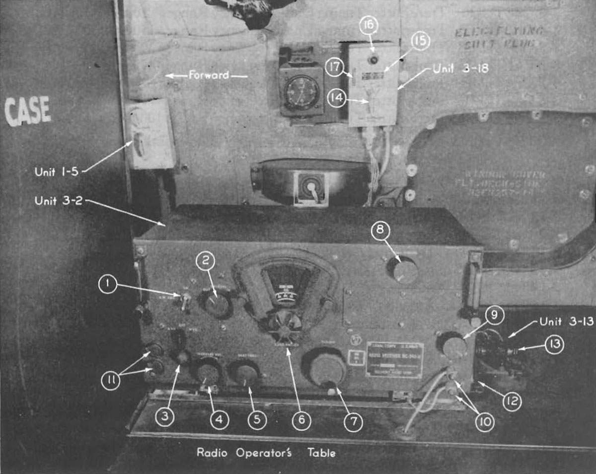
| -//- 3-2 |
One BC-348-H Receiver. Tuning range 1500 KC to 18,000 KC. Page 113. |
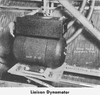
| -//- 3-10 |
One PE-73-C Dynamotor (Liaison). Page 118. |
| -//- 3-13 |
One J-37 Transmitting Key. Page 113 |
| -//- 3-14 |
One RL-42 Antenna reel. |
| -//- 3-15 |
One MC-163 Antenna Fairlead. |
| -//- 3-16 |
One F-10 Trailing Antenna
One W-T-7A, SC-D-3338 Antenna weight. |
| -//- 3-17 |
One X41-B10A16 Antenna Transfer Switch. Page 116 |
| -//- 3-18 |
One BC-461 Antenna reel control box. Page 113. |
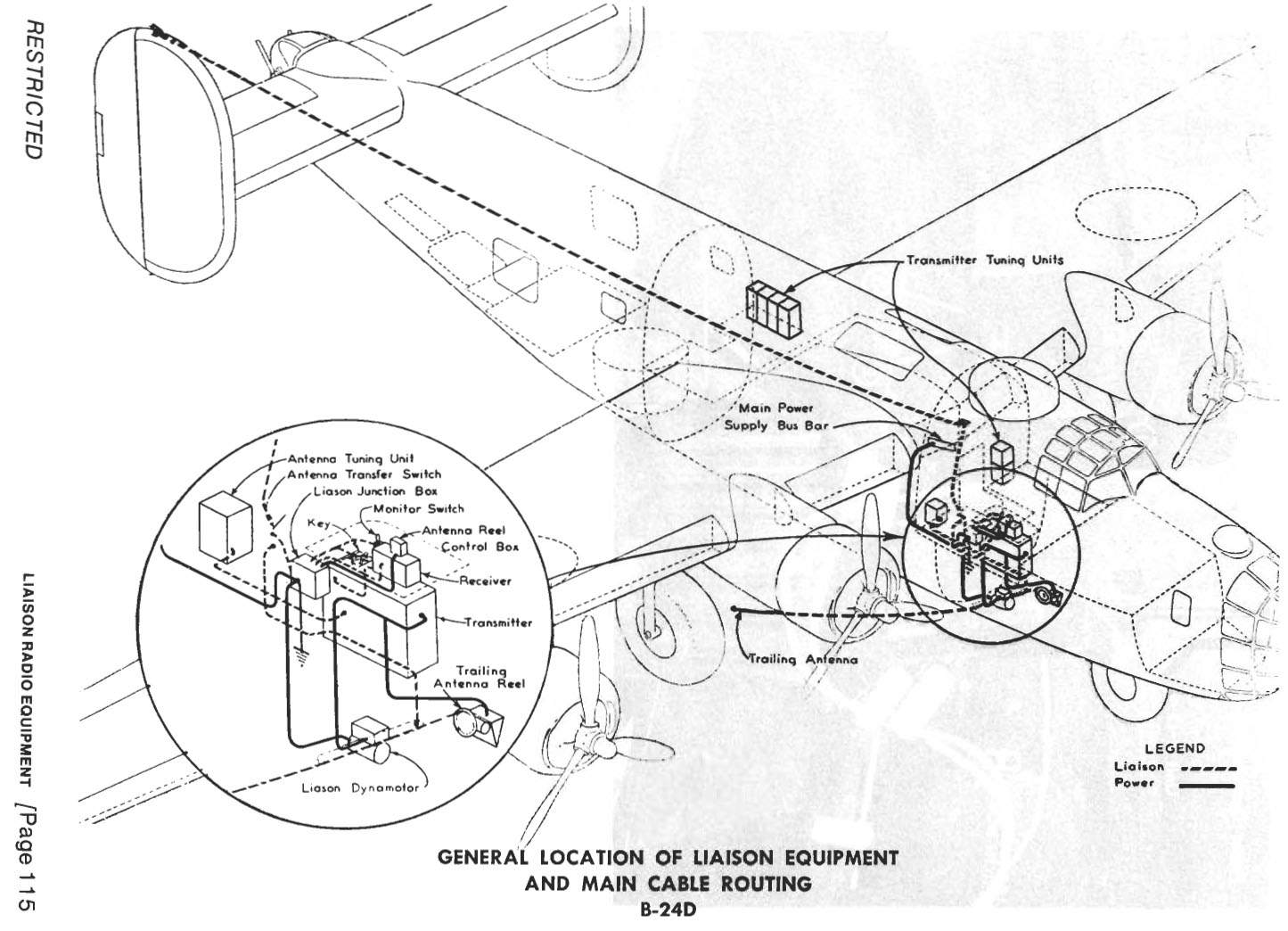
These units are located through the-airplane as follows:
BC-375-D Transmitter Unit 3-1 — Under radio table, right side of flight deck behind Co-Pilot.
Two CS-48 Stowage boxes for transmitter tuning units—Left rear of flight deck.
Two TU Tuning Units in flight deck stowage.
Four CS-48 Stowage boxes—Above bomb bay, left side, aft of wing center section.
Four TU units in stowage above bomb bay.
One BC-348-H Receiver—On operator's table behind Co-Pilot.
One PE-73-C Dynamotor—Under flight deck, forward of anti-icer motors.
One J-37 Key—On operating table.
One RL-42 Antenna reel—Under flight deck, forward of dynamotor on flight deck floor brace.


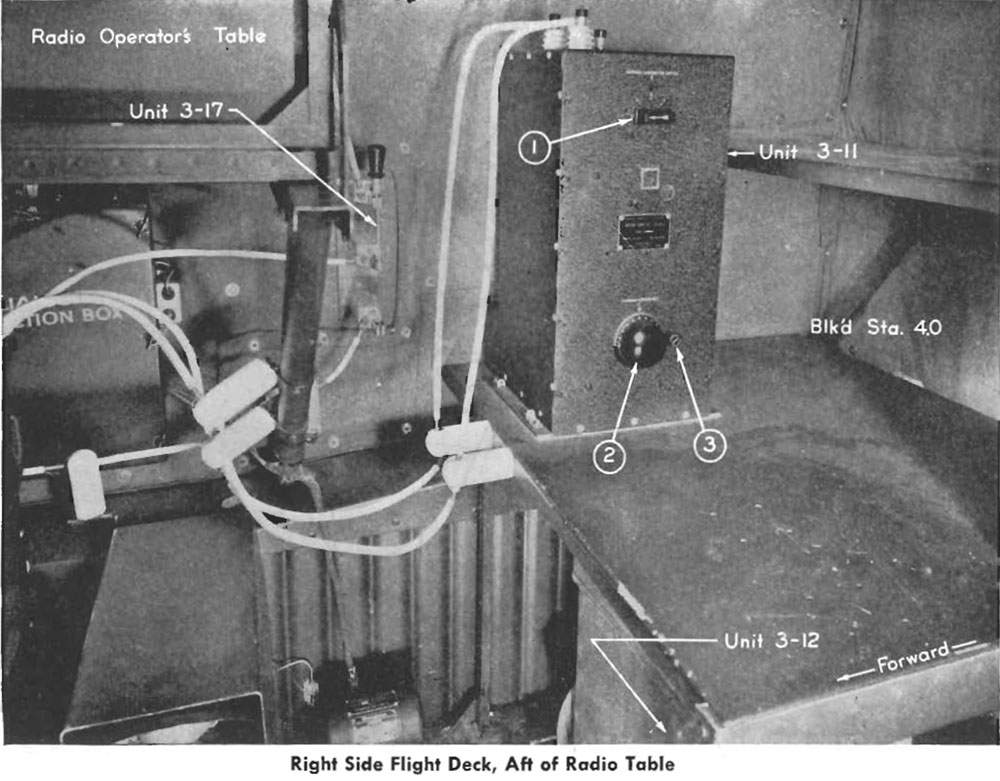
Right Side Flight Deck, Aft of Radio Table (Page 116)
One MC-163 and F10 Antenna Fairlead and trailing antenna—Under flight deck, right side.
One BC-306-A Antenna Tuning Unit—Right rear of flight deck, aft of radio table.
One SCR-211-D Frequency Meter—Right rear section of flight deck. Portable equipment used for frequency checking.
BC-461 Antenna reel control box—Right wall of cabin above radio table.
X41-B10A16 Antenna Switch - Right wall of cabin, aft of radio table. The liaison equipment is used generally for long distance communication between the airplane and base or airplane and ground stations. It is used primarily for reporting ship position or flight progress. Control of liaison equipment is held by the Radio Operator.
Liaison Equipment Operation—The liaison receiver face contains nine controls, as follows (see Page 128):
1. C.W. Oscillator—"OFF" and '"ON" Switch—upper left.
2. Crystal "IN" and "OUT" Switch—to the right of C.W. Oscillator switch.
3. Power switch: ("A.V.C.") or ("M.V.C.") below oscillator switch.
4. Volume Control—lower left side of face.
5. Beat frequency pitch control—to the right of volume control.
6. Band change switch—lower portion of dial.
7. Tuning control—below and to the right of dial assembly.
8. Dial light brilliancy control—upper right.
9. Antenna Alignment—extreme right center.

Liaison Transmitter, Under Radio Table (Page 117)
In addition to the above nine controls, there are four connectors located on the face of the receiver. At the extreme right in the lower corner are the terminals for the antenna and ground (10). At the extreme lower left are two jacks for headset attachment plugs PL-55 (11).
The liaison receiver is in operation when the switch (3) is in either "AVC" or "MVC" position. The tuning control is operated with the power switch in the "MVC" position. After location of the desired signal, adjust volume to desired intensity and throw power switch to "AVC" for automatic maintenance of desired volume. For reception with the liaison receiver, the "Monitor Switch" (12) mounted on the operator's table between the J-37 key (3-13) and the receiver, must be in the "Normal" position. The "Monitor" position is used when it is desired to operate the liaison receiver for a check on the liaison transmitter tuning or adjustment. For further details on this check, see "Liaison Transmitter" which follows.
Band switching is accomplished by turning of the control knob (b). The band in use is indicated through the dial mask.
The receiver dynamotor is contained within the receiver and is only accessible by removing the receiver from its case.
Liaison receiver output is available at any interphone junction box in the airplane.
For CW reception the beat frequency oscillator with its manual pitch control may be used either with or without the crystal filter at the option of the operator.
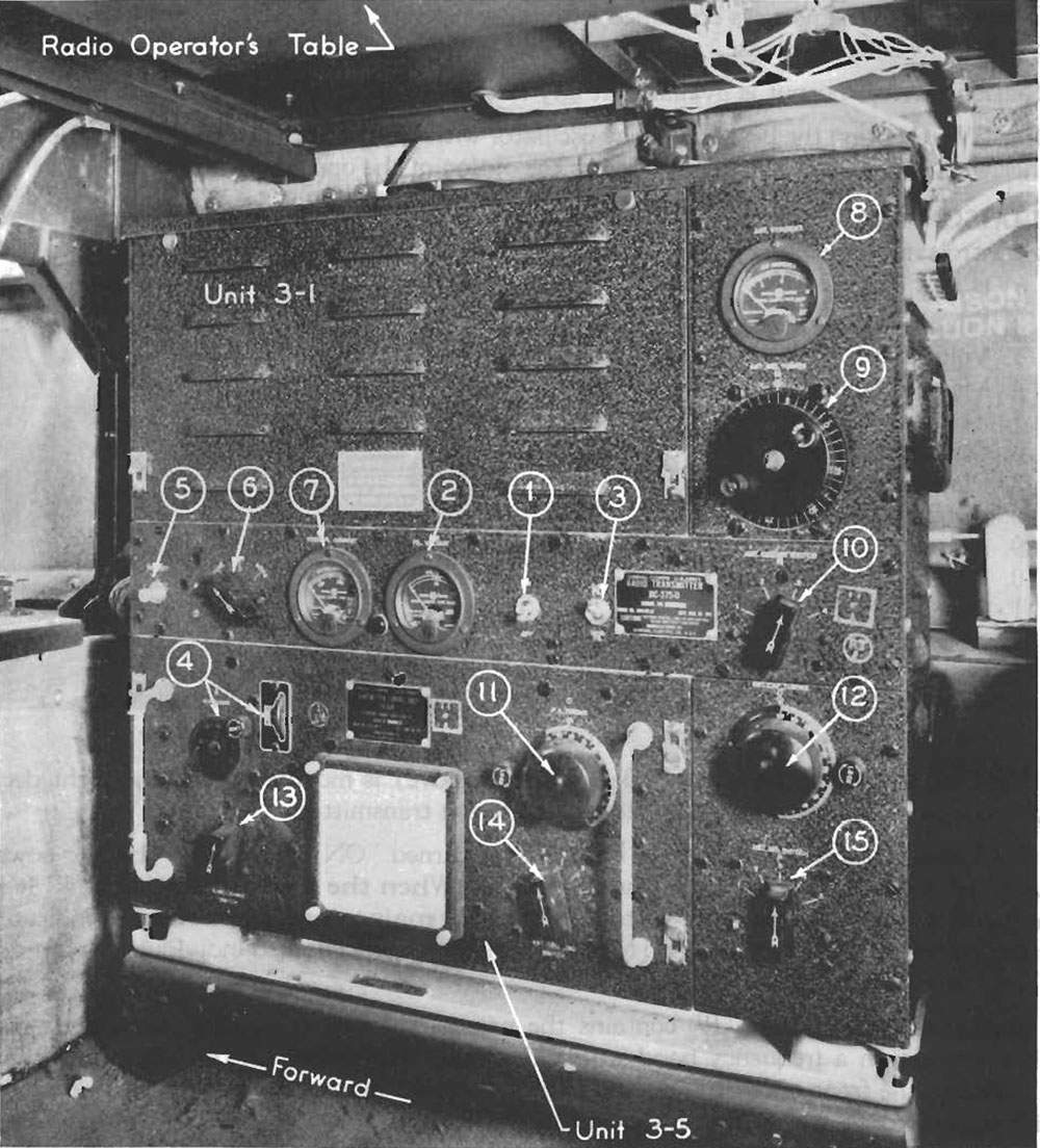
LIAISON TRANSMITTER — The liaison transmitter Unit 3-1. Page 117, has the following controls and indicators on the front of the panel:
1. Power Switch
2. Filament Voltmeter
3. Voltmeter Switch
4. Master Oscillator Tuning Controls
5. Test Key
6. Output Control Switch
7. Plate Current Meter
8. Antenna Current Meter
9. Antenna Tuning Control (Inductance)
10. Antenna Circuit Switch
11. Power Amp Tuning Dial
12. Antenna Tuning Control (Capacity)
13. Band Change Switch
14. Antenna Coupling Switch
15. Antenna Inductance Selector Switch
The Liaison Dynamotor Unit 3-10 (see photo right) is mounted under the flight deck right side, and supplies high DC plate voltage to the transmitter.
The Liaison transmitter Unit 3-1 Page 117, is turned "ON" and "OFF" by the power switch (1) mounted on the face of the transmitter. When the transmitter is "ON" it is important that the filament voltage be closely maintained at 10 volts as indicated on the voltmeter (2). The C.W. and Modulator filaments are checked individually by means of a selector switch (3).
Each tuning unit, Page 119 contains the necessary tuned or tunable circuits to permit operation on a frequency band within the limits as specified on the calibration chart attached to the front of the tuning unit.

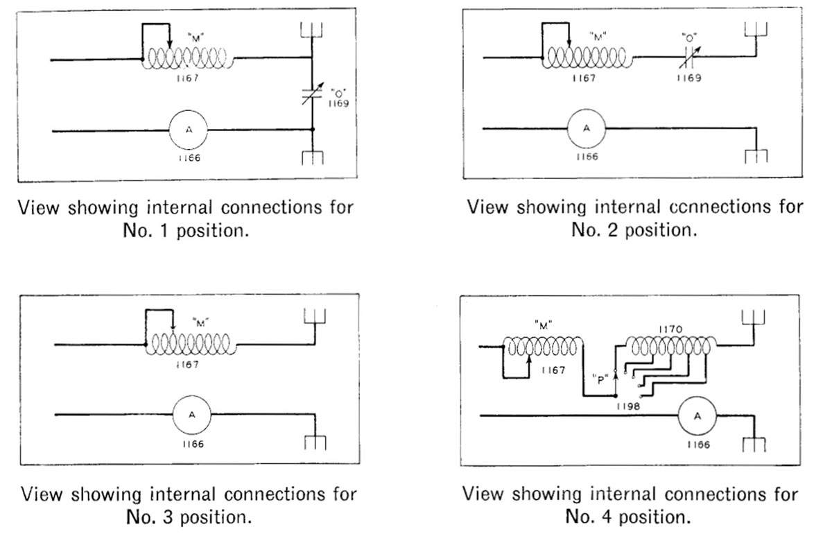
ANTENNA INDUCTANCE SELECTOR SWITCHES B-24D
2012.09.26
<< | >>
November 06 2012
Nice website! I like your photocopied pages of maintenance manuals such as the B-24 General Systems. I sell a number of the items you have listed here on your site. Is there much for sale in Russia for WWII airplanes?
Curtiss Aldrich, owner
aviation-antiques.com
-- Curtiss Aldrich
| 

