Figure 231 - ENGINE ELECTRICAL ACCESSORIES
17 ELECTRICAL SYSTEM
a. DESCRIPTION.
(1) GENERAL. - A single wire, 28-volt, grounded type, partially shielded electrical system is provided. Conventional in plan, the electrical system consists of the engine ignition and starter circuits, the generator and battery circuits, and the lighting and auxiliary circuits. A two-wire system is used in the bomb release circuits. Much vital equipment such as propellers, radios, and instruments depend upon the electrical system. Therefore the system must be in complete operating condition before take-off. There is sufficient capacity in generators and batteries so that all equipment necessary to flight may be operated with one of the generators '' out''. The batteries are adequate for a short flight if the generators fail, and all electrically operated equipment not essential to flight is turned OFF to conserve battery power.
(2) GENERATORS AND BATTERIES.
(a) GENERAL. - Each engine has a 28-volt generator (figure 120) whose output is controlled by a voltage regulator and reverse current relay. Two 12-volt batteries connected in series serve to start the engines in the absence of an outside source of power.
(b) GENERATORS. (See figure 231.) - Type 0-1 28-volt generators are used. A reverse current relay switch (sometimes called "generator cut-out" or "line switch") and ammeter shunt are installed in each nacelle. The voltage regulators and a panel containing two generator ON-OFF switches, two ammeters, a voltmeter, and a voltmeter selector switch are located to the right of the upper gunner's position The generators carry the load after the engines are started. Therefore the ammeters merely show the amount of current supplied to the system. The continuous electrical load is comparatively low in relation to the generator capacity.

Figure 232 - INSTALLED BATTERIES

This additional capacity is necessary to care for emergency conditions. During long flights where the batteries become fully charged and there is little load on the electrical system the ammeter readings for the generator may be low. This is a normal condition and does not indicate that the generator, regulator, or relay switch is faulty. If the generator shows approximately normal voltage on the voltmeter in the gunner's cockpit, the voltage regulator and the generator are in working condition. During normal flight all generator switches should be ON so the generator capacity will be available immediately when required. No advantage is gained by having switches OFF.
(c) BATTERIES. (See figure 232.) -Two 68 ampere-hour type D-6A, 12-volt batteries, connected in series, are installed in the section of the fuselage forward of the front bomb bay at Station 75. A battery disconnect relay is controlled by a switch on the pilot's electrical panel. The function of the batteries is to furnish energy to start the engines (when external power is not available) and to operate electrical circuits while the engines are not running. Fumes from the batteries are carried by air through tubing to a battery sump. The sump consists of a glass jar filled with alternate layers of baking soda and felt. The fumes are neutralized by the soda. The sump is located on the right-hand side of the nose wheel well.
(d) GENERATOR CONTROL BOX. - Mounted on the inside of the fuselage to the right of the upper gunner just forward of the gunner's switch box is a metal box containing two voltage regulators (one for each generator). Purpose of the voltage regulators is to maintain constant voltage regardless of variations in the speed of the generators and conditions of varying electrical loads. Constant voltage is necessary for much of the electrically operated equipment on the airplane. Voltage regulation is accomplished automatically by controlling the amount of resistance inserted into the field circuit of the generator. A voltage regulator is a precision equipment and must be handled with care.

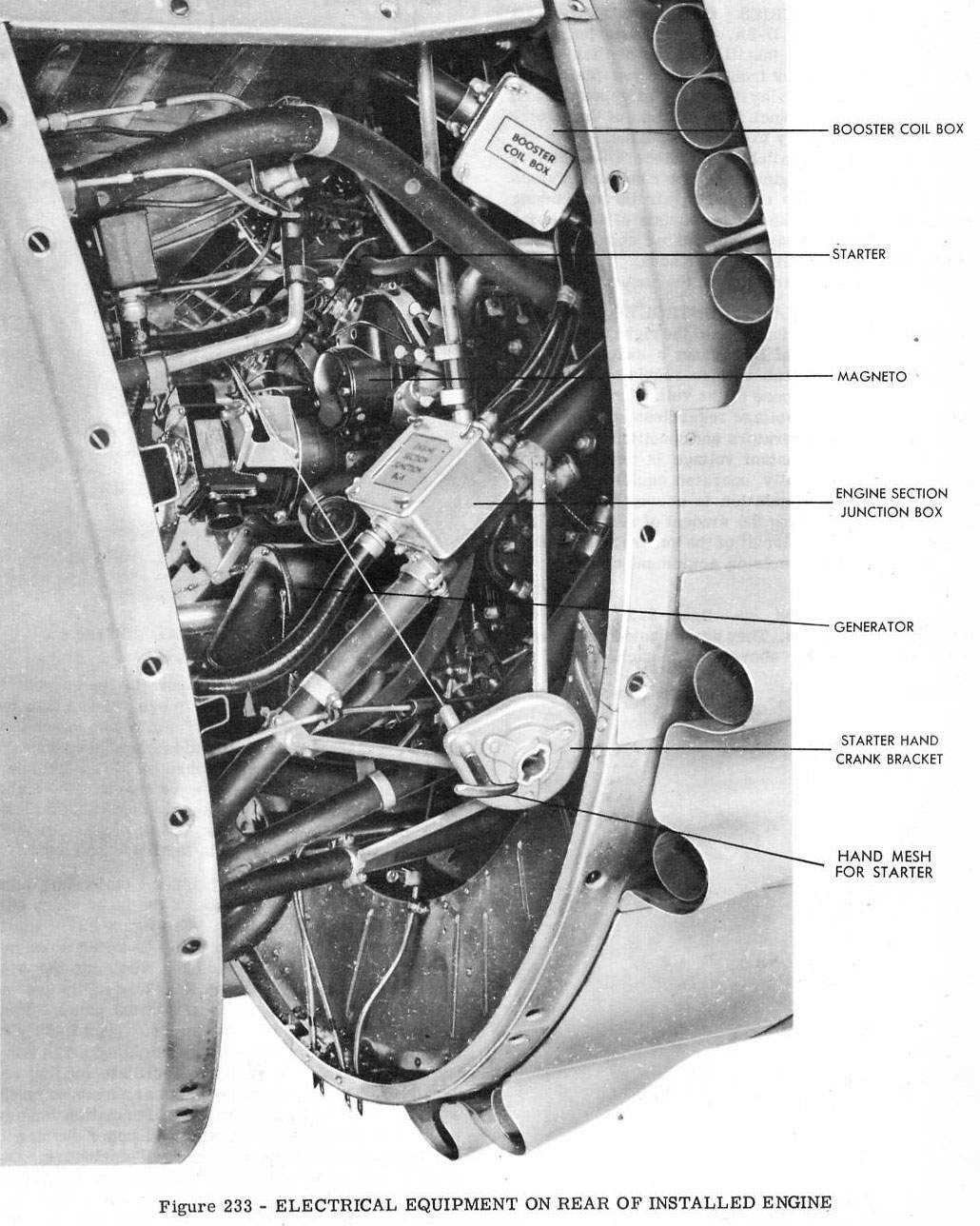
(3) MAGNETOS. (See figure 233.) - Each engine has two magnetos. They are mounted on the rear of the engine slightly above and to each side of the starter. Their function is to generate the current to furnish the spark to the spark plugs. The magnetos incorporate eight lobe breaker cam points which turn at 7/8 crankshaft speed. Pivotless type breakers are used. Both magnetos are timed on No. 1 cylinder, after which they operate with fixed timing. The right-hand magneto fires the front spark plugs and the left-hand magneto fires the rear spark plugs. Booster coils, mounted on the engines, facilitate starting.

(4) LIGHTS. - Two ST-1220AF-24 1anding lights are installed on the under side of the inner wings outboard of the engine nacelles. (See figure 234.) Built-in drive motors cause these lights to swing down and forward when turned ON and back flush into the wing when OFF. Control switches for these lights are installed on the pilot's upper electrical panel. Each cockpit is lighted by type A-6 lights. Type C-5 lights are used for the instrument panel lighting. The bomb racks have extension lights to facilitate loading and servicing. Type A-8 running lights are mounted on the wing tips and vertical stabilizer. Formation keeping lights are mounted on the wing and upper surface of the fuselage aft of the rear cockpit enclosure. One upward and three downward recognition lights are mounted on the fuselage. They are operated from a control box in the pilot's cockpit. They are wired so that any combination of downward lights may be selected. Wiring to the tail navigation light allows it to be used both as a navigation and "resin" light. Alternate red, green, and clear lenses are provided. An access door permits changing of the lens.

(5) EXTERNAL POWER FOR STARTING ENGINES AND FOR CHECKING EQUIPMENT. - Toensure that batteries will be charged at take-off so they will be adequate for emergency conditions, use an external electrical supply such as a battery cart or portable 28-volt power plant to start the engines. Plug the external power supply into the external power receptacle on the left side of the nose wheel well. (See figure 235.) If an external power supply is not available, an energizer may be used to start the engines. If a portable power plant is used, it may be connected to the airplane a short time before take-off and the main line and battery switches turned on so the batteries will charge. Use external power for checking of electrically operated equipment on the ground. If an external power supply is being used, all electrically controlled units in the airplane may be operated with the main battery switch and the master ignition switch OFF. To start the engines on the external power supply, the master ignition switch must be ON. When changing over from the external power supply to the airplane's batteries with the engines running, the main battery switch must be ON before the external supply plug is disconnected.
(6) SWITCHES.
(a) GENERAL. (See figure 236) - Mounted on the left side of the pilot's cockpit, the ignition switch is separately shielded from other electrical equipment. Most other circuits are controlled by standard Army Air Forces toggle switches. All switches are OFF in the UP position except those which control the emergency alarm bell and the jettison of the small bombs container.
(b) MAIN BATTERY SWITCH. - Conventional operation of the main battery switch on the pilot's lower electrical panel controls the circuit from the airplane's batteries by operating a master relay located on a box below the batteries at Station 75. (See figure 237.) If the batteries are used as a source of power, both the main battery switch and the master ignition switch must be ON before any of the electrically controlled units can be used.

(c) IGNITION SWITCH. - The ignition switch is located in the upper left corner of the pilot's instrumentpanel. (See figure 236.) The ignition switch unit incorporates a master ignition switch and two individual engine switches as follows:
1 MASTER IGNITION SWITCH. - The master ignition switch has two positions controlling circuits as follows:
OFF. - All magneto circuits are closed (grounded) and the circuits to all electrically controlled units in the airplane are open (magnetos and all electrically controlled units are inoperative).
ON. - All magneto circuits are open (ungrounded) 1 and the circuits to all electrically controlled units are closed (magnetos and all electrically controlled units are operative).
2 INDIVIDUAL ENGINE SWITCHES. -Each individual engine switch controls the ignition of one engine and has four positions controlling circuits as follows:
OFF. - Both magneto circuits are closed (both magnetos inoperative) with the master switch ON or OFF.
L. - The left magneto circuit is open (left magneto operative) and the right magneto- circuit is closed (right magneto inoperative) with the master switch ON.
R. - The right magneto circuit is open (right magneto operative) and the left magneto circuit is closed (left magneto inoperative) with the master switch ON.
BOTH. - Both magneto circuits are open (both magnetos operative) with the master switch ON.
(d) SWITCHES ON PILOT'S UPPER ELECTRICAL PANEL; (See figure 238.)

1 WARNING HORNRELEASE SWITCH. - The warning horn release switch is provided to silence the horn if it is desired to close the throttles when the landing gear is not latched in landing position. The horn circuit is automatically reset after operation of the release switch opening the throttles, and if the throttles are again closed, the horn will sound until the horn release switch is operated.
NOTE
If only one throttle is closed with the landing gear not latched in landing position, the warning horn release switch will silence the horn for only an instant. To quiet the horn, the throttle must be opened'beyond the horn operating position.
2 LANDING GEAR WARNING LIGHTS SWITCH. - A green signal light is provided to indicate that the landing gear is down and latched in landing position. A red signal light will show at all other times. These lights may be made dim or bright by operation of the warning lights switch.
3 GUNNER CALL LIGHT SWITCH. -Conventional operation of the gunner call light switch will illuminate the call light on the gunner's electrical panel.
4 HEATING SYSTEM SWITCH. - Conventional operation of the switch will energize the fuel ignition plug of the heating and vent system heating unit.
5 PROPELLER FEATHERING SWITCHES. - A switch is provided for each propeller and is operated by pushing the respective switch for the propeller to be feathered. The switch will automatically release when the propeller blades reach the
2 TRIGGER SWITCH. - The fixed forward guns are electrically fired (selector switches must be ON) by a trigger switch on the control wheel. This switch operates a relay controlling the gun firing solenoids.
(j) FUEL QUANTITY GAGE SELECTOR SWITCH. - The airplane is equipped with a fuel quantity gage selector switch. This switch enables the pilot to connect the fuel indicator to the liquidometer unit in any gasoline tank.
(k) RELAY SWITCHES (sometimes called generator cut-out). - A relay switch is mounted in a metal box in each nacelle on the aft side of the firewall above and left of the fire wall junction box. The relay switches connect the generators to the airplane electrical system when the generator voltage is sufficiently high. However, the relays will close only when the generator switches (in the gunners' cockpit) are closed. The relay switches open automatically in case the generator voltage becomes lower than the system voltage causing a reverse current to flow.
(1) GUNNERS' SWITCH BOX (sometimes called the junction box). - Mounted on the inside of the fuselage to the right of the upper gunner aft of the generator control box is a metal box which comprises mounted two ON-OFF generator switches, two ammeters, one voltmeter, a voltmeter selector switch, and pilot to gunners' call lights.
(7) MAIN FUSE PANEL. (See figure 240.) -Mounted on the left side of the fuselage in the nose wheel well between Stations 37 and 75 is the main fuse panel. Access to the area is through a hinged cover on the inside of the nose wheel well. Its cover is attached by Dzus fasteners.
(8) MISCELLANEOUS ELECTRICAL EQUIPMENT.
(a) EMERGENCY ALARM. - An emergency alarm bell is installed at the upper rear gunner's station. It is controlled by a switch in the pilot's compartment.
(b) ELECTRIC DRIVES. - Electric drives are used for extending and retracting the landing lights, and for operating the fuselage fuel tank booster pump and the propeller feathering pumps.
<< | >>
|