Aviation of World War II


|
|
Aviation of World War II |
|
|
Soviet Union | Lend - Lease | Facts | Forum | Germany | Japan | R A F | U S A A F | Other | Photos |
|
|
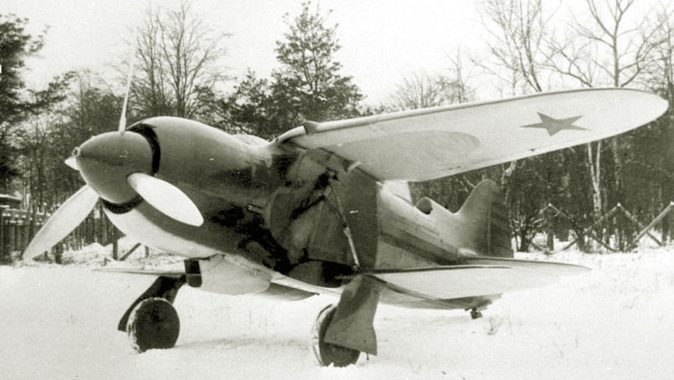
IS-1 (2)FighterShevchenko, Nikitin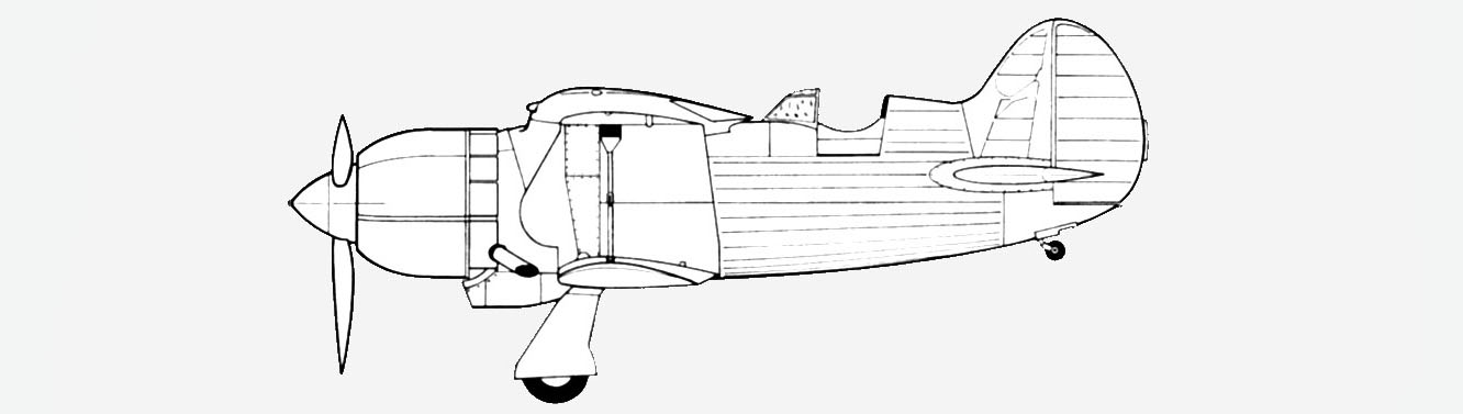

The IS-1 was an experimental aircraft built to study a previously unprecedented scheme and test the wing retraction mechanism and landing gear in flight. Outwardly, the IS-1 had some similarities with the I-153. The lower wing consisted of a center section and folding consoles. By means of a lifting mechanism installed in the fuselage, the center section rotated on the hinges of the attachment to the fuselage and folded the lower wing. The lifting mechanism, in turn, consisted of a hydraulic cylinder and two rocker struts. Working pressure (60 atm) was created by a pump mounted on the motor. The console had two spars riveted from duralumin profiles with a wall. Sheathing made of sheet duralumin, reinforced with stamped ribs. The lower center section consisted of two truss welded spars and a central tube for attaching the wings of the lifting mechanism. The ribs and lining of the center section are duralumin. The undercarriage and tail skid were removed at the same time as the wing was retracted. The aircraft provided for the installation of four machine guns ShKAS 7.62 mm, located in the center section of the upper wing. The fuselage, welded from chromansile pipes, was a power truss with an outer duralumin frame and mixed skin. The front compartment consisted of four frames interconnected into a farm. In place of the center section, a power basket was attached. A rod for lifting and releasing the wing and landing gear is installed in its compartment. On the outer sides of the basket there were attachment points for the lower center sections. On the front frame are the attachment points of the motor mount. On the fourth - the attachment points of the rear fuselage. Between the first and second frames is the front gas tank, and between the third and fourth is the rear. The rear compartment is braced with wire crosses. The pilot's compartment had additional rods for installing the seat and floor. The outer skin of the fuselage was divided into front and rear sections. The frame of the tail section was made of light duralumin frames, and longitudinal profiled stringers and covered with ACT-100 canvas. The upper wing consisted of a gull-shaped center section and two consoles. The wing is of a two-spar design with a working duralumin skin. Truss-type spars welded from chromansile pipes. The ribs of the wing, stamped from duralumin, were attached to the spar with steel clamps. In the skin of the center section of the upper wing there were power hatches for servicing machine guns. The stabilizer had two spars, on which stamped ribs were typed. The stabilizer was attached to the fuselage with four bolts, which made it possible to change the installation angle of the stabilizer on the ground in the range from +2 to -4 °. The keel is a removable two-spar design, attached to the fuselage at four points. Cantilever chassis with shock absorption and normal brake wheels measuring 700×150 mm. An aircraft-mounted crutch, unguided, orienting, lockable in neutral position. Cleaning and release of it was carried out with cables. The crutch is equipped with a pneumatic shock absorber. Aircraft control is mixed. Elevator and ailerons - rigid, consisting of duralumin pipes and rocking chairs. Steering wheel control - cable. |
|
|
| |||||||||||||||||||||||||||||||||||||||||||||||||||||||||||||||||||
 Aircraft
 Combat Use